In the HPCL Rajasthan Refinery Limited, the Slop oil is transferred from Sumps to Slop transfer pumps through Sump Pumps with a rated flow of 10 m3/hr. At any time, the slop will be transferred using the pump on one of the Sumps while the pump on the other Sump will be idle. The discharge from the Sump pumps are routed to suction of 2 nos. Slop transfer pumps with a rated flow of 5 m3/hr each. The slop transfer pumps are Triplex Plunger pumps operating at constant speed of 268 RPM. The discharge of the Slop transfer pumps is connected with a 12” pipeline. The discharge pressure of the slop transfer pump can vary from min. 33 kg/cm2 to max. 83 kg/cm2 depending on the static pressure at the tee connection on the 12” Oil pipeline.
Hiro Nisha Systems Pvt. Ltd. entrusted iFluids Engineering to conduct a Pulsation and Vibration Analysis of Slop Oil transfer pumps and Piping network in accordance with API 674 Design Approach 2.
What is Pulsation?
Pulsation generally occurs when a liquid’s motive force is generated by a reciprocating or peristaltic positive displacement pump, and is most commonly caused by the acceleration and decelerations of the pumped fluid. This uncontrolled energy appears as pressure spikes and usually leads to damaged seals, gauges, diaphragms, valves and piping joints. The visual manifestation of pulsation is vibration.
Solution
The solution is to install a pulsation dampener or surge suppressor. They are the most effective choice and a cost-efficient way to prevent damage caused by pulsation. The dampener should be installed as close as possible to the pump or quick closing valve and is charged to 85% of the liquid line pressure. It is important to specify the correct pulsation or surge suppressor, and this requires careful calculation. Pulsation study provides the clear calculation with graphical and visual results to prevent from pulsation and its causes.
SIGNIFICANCE OF UNDERTAKING PULSATION STUDY?
Pulsation can cause catastrophic failure of pipe systems and damage expensive equipment. Properly addressing such issues at the design stage is essential.
It allows the engineer to better understand and predict the dynamic behaviour of the pipe system. When undesirable pulsations are identified at the design stage different strategies to reduce the pulsation can be evaluated. These may include surge install surge suppression equipment, modifying the design, or modifying the system operation.
Sometimes the undesirable pulsations are not discovered until the system is built. In such cases Pulsation study can provide critical insight into the cause of the problem and allow the engineer to assess design and operational modifications to resolve the issues.
PURPOSE
The purpose of the pulsation study is to the investigate pressure variations caused by the operation of Triplex plunger pumps and to confirm that the selected dampeners are adequate to keep the peak-to-peak pressure pulsations within the allowable limits calculated in accordance with API 674 Design Approach 2.
The piping network is divided into two parts, the Suction pipe network comprising of the piping between sump pumps and the PD transfer pumps tagged as “Upstream” models and the discharge pipe network operating from discharge of the PD pumps up to the tie-in with the 12” Oil pipeline tagged as “Downstream” models.
Pulsation study is carried out for the suction pipe network with PD pump suction pressure of 7 kg/cm2 and separate models are analyzed for each of the sump pumps operating while the other is idle. Pulsation study is carried out for the PD pumps discharge pipe network for the min. discharge pressure of 33 kg/cm2 and max. discharge pressure of 83 kg/cm2.
APPROACH OR METHODOLOGY
A typical Pulsation study is conducted as per the following steps:
Step 1: To study the given system and find out the places where pulsation can occur (At design Stage), or get the required details where pulsation occurs (At existing system).
Step 2: System modelling using software (AFT Impulse).
Step 3: Provide the required details of pump, piping network and all other components in the system.
Step 4: Provide the fluid characteristics, flow and pressure values.
Step 5: Run the model with Static and transient features available in software.
Step 6: Evaluate the output values and graphical results.
Step 7: Optimization of system design and operations (Until the pulsating effect are achieved as minimum.)
Step 8: Prepare the detail report to client with assessment of design and modifications to resolve the issues.
PULSATION ANALYSIS
The general steps of pulsation analysis in PD pump systems involve the following:
- Creation of the model: Definition of piping and process equipment. A Steady State run is performed in order to check that the system is defined correctly.
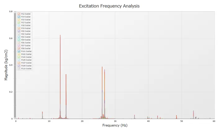
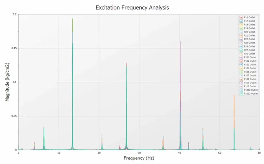
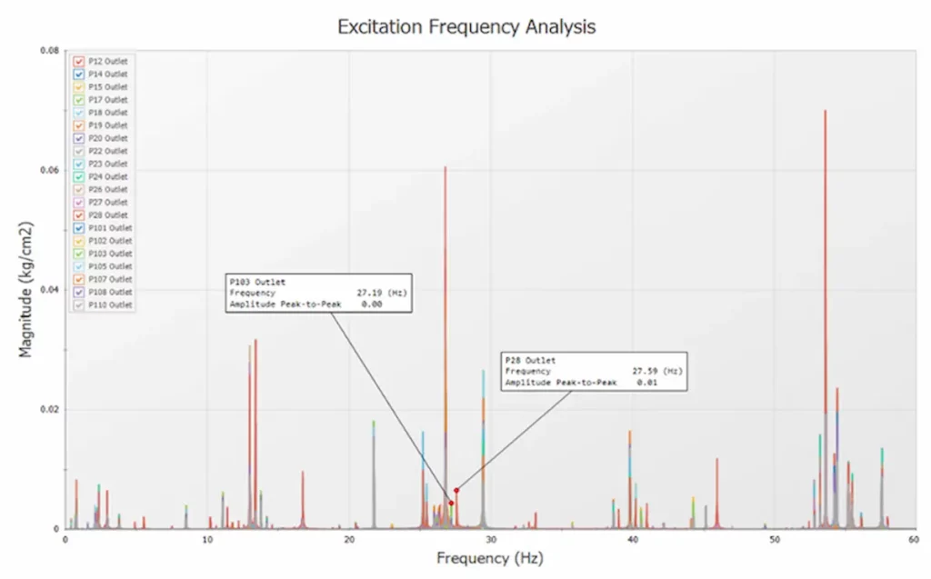
- Determination of network Natural frequencies. It is done by striking the system with a very short pulse (sudden increase of flow rate) to determine excitation frequencies.
- Generation of the Excitation frequency graph and selection of Natural frequencies for further analysis. For a defined frequency and constant speed, the PFA module calculates the PD pump speeds (RPM) that will excite the chosen frequencies. These speeds (RPMs) are commonly referred to as ‘worst-case’ pump speeds because they match up with the harmonic frequency of the system and cause the most vibrations when operating at that frequency. However, as the PD pumps run at constant speed of 268 RPM, that speed and the corresponding harmonic frequency, if applicable, will be considered for evaluation of pulsation level.
- For constant RPM, a scenario is created that model the pump operating at the specified speed.
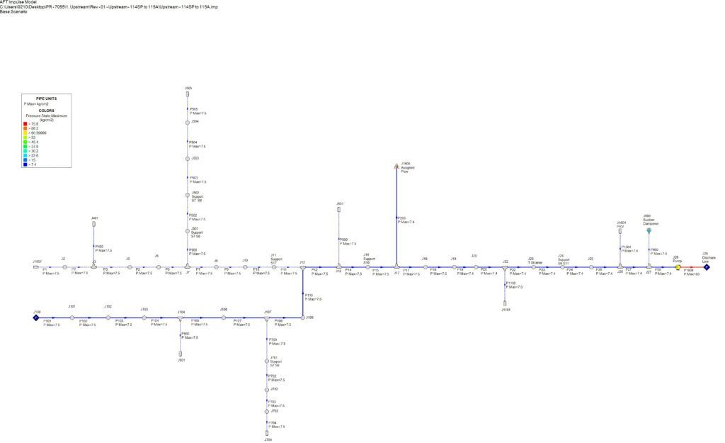
Static Result – Upstream Model
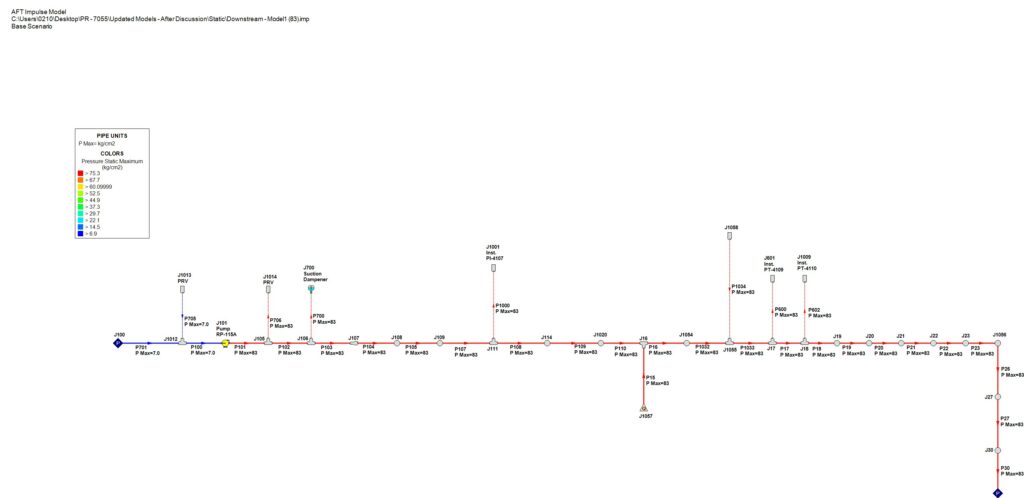
Static Result – Downstream Model
Natural Frequency Analysis – Upstream Model
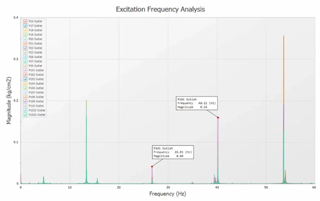
Natural Frequency Analysis – Downstream Model
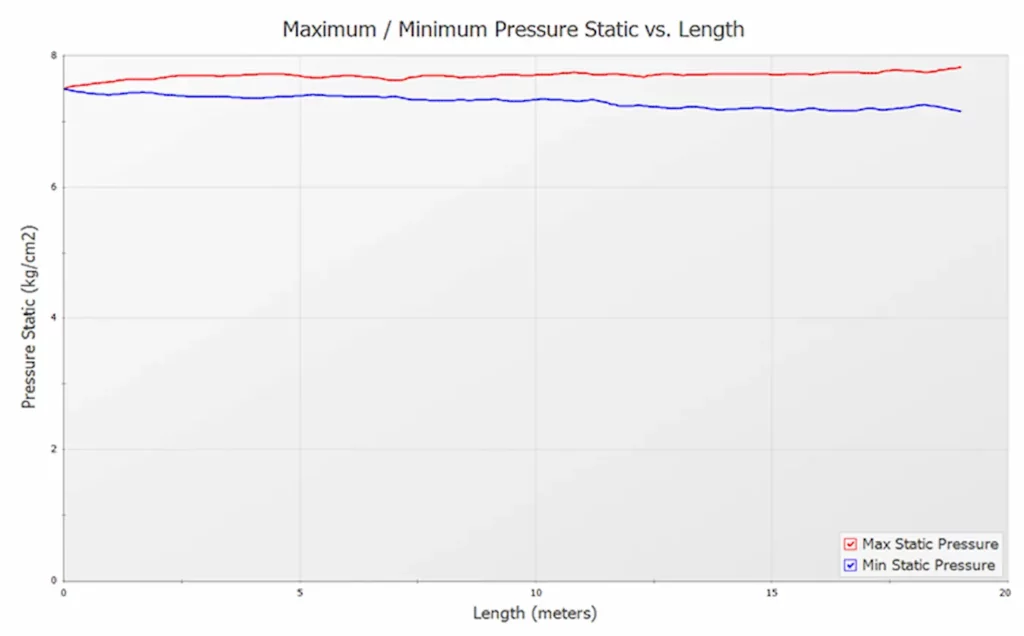
Maximum and Minimum Pressure Profile – Upstream Model
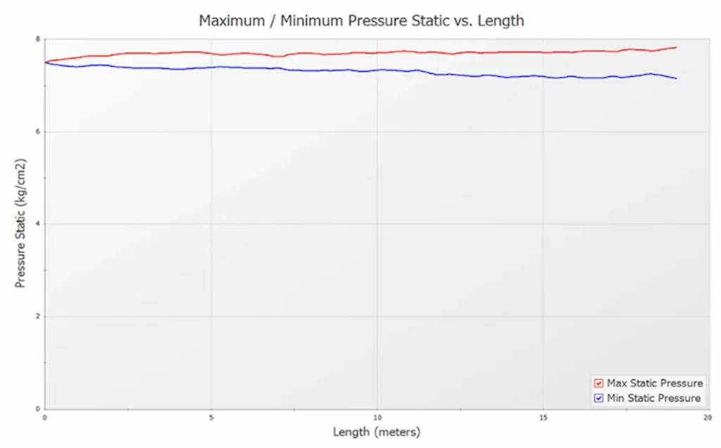
Maximum and Minimum Pressure Profile – Downstream Model
Pressure Variations with Dampener – Upstream Model
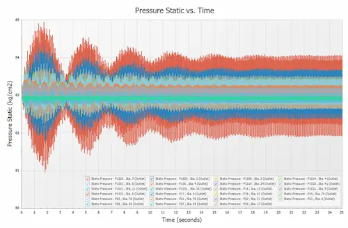
Dampener Impact – Upstream Model
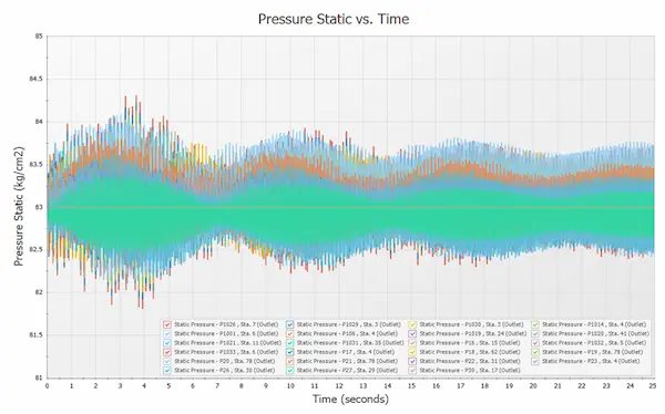
Dampener Impact – Downstream Model