
The overall objective of the Lightning Protection Assessment Study is to check and ensure that the entire plant area including structures/buildings and tank farms are safe from the lightning phenomena. The Study is carried out based on Lightning Protection Standard OISD-GDN-180 & IEC 62305.
Lightning Protection Study Methodology
A lightning strike is an electrical discharge between the cloud and the earth. It is a natural, unpredictable phenomenon having an independent current source. The lightning has number of components such as lightning current, very high peak current, charges and a specific energy with a wave shape of 10/350 μs.
Lightning is a naturally occurring phenomenon that often causes severe damage to life and property. Direct hits may cause structural failure, whereas indirect hits through inductive or capacitive coupling, may affect the reliability and integrity of electrical and electronic equipment within the structure.
Conventional method of lightning protection system consists of lightning masts / rods exposed and placed at the highest levels of structures and connected through downward conductors to a grounding system. A design method is normally used to identify the most suitable locations for the lightning masts / rods, based on the area of protection offered by each one.
There are different methods of lightning protection systems. Examples of existing methods include geometrical constructions, such as the “Protective Angle Method” and “Rolling Sphere Method” which is based on “Electro geometric” models (EGMs). The rolling sphere method is a simple means of identifying areas of a structure that need protection, considering the possibility of side strikes to the structure.
There are several methods out of which some of the commonly employed methods for lightning protection are:
- Lightning Rods: Also known as air terminals or lightning conductors, lightning rods are installed at the highest points of structures to intercept lightning strikes. They are typically made of conductive materials like copper or aluminum and provide a path of least resistance for the lightning current, directing it safely into the ground.
- Grounding Systems: Proper grounding is essential to dissipate the lightning energy safely into the ground. Grounding systems consist of conductive materials such as copper or galvanized steel rods, buried in the earth and connected to the lightning rods and other metallic components of the facility. These systems help prevent dangerous ground potential rise and reduce the risk of damage to equipment and personnel.
- Surge Protection Devices (SPDs): SPDs are installed in electrical systems to suppress transient voltage surges caused by lightning strikes. They act as a barrier, diverting excess voltage away from sensitive equipment, such as control systems, computers, and instrumentation. SPDs help prevent equipment damage and operational disruptions due to lightning-induced power surges.
- Bonding and Shielding: Bonding involves connecting metallic components and structures to ensure electrical continuity and equipotential grounding. Bonding conductors are used to connect various metallic parts, such as tanks, pipes, and equipment, reducing the potential for differences in electric potential and the risk of sparks or arcing. Shielding involves the use of conductive materials or mesh around critical equipment and control rooms to provide electromagnetic shielding from lightning-induced electromagnetic interference.
- Lightning Protection for Tanks: Floating roof tanks and fixed roof tanks can be vulnerable to lightning strikes. To protect them, bonding conductors and static dissipaters are installed on floating roofs, while fixed roof tanks may have lightning rods and bonding systems. These measures help prevent sparks and potential ignition sources within the tanks during a lightning event.
- Surge Arresters: Surge arresters are devices that protect electrical equipment from voltage surges caused by lightning. They are typically installed at strategic points in the electrical distribution system, such as substations, switchgear, and control rooms. Surge arresters divert excess voltage to the ground, safeguarding sensitive equipment.
- Lightning Warning Systems: Lightning warning systems utilize advanced technology, such as lightning detection sensors, to monitor the approach of thunderstorms and provide early warning of potential lightning strikes. These systems can trigger alarms, activate shutdown procedures, and help ensure personnel safety by evacuating outdoor areas.
In many cases, certification of a lightning protection system is required by local building codes or insurance regulations. Certification ensures that the system has been designed and installed in accordance with recognized industry standards and meets the minimum safety requirements.
The four essential elements of a lightning protection system are:
- Air terminals or lightning rods,
- Conductor cables or down conductors,
- Ground rods or plates, and
- Bonding or equipotential bonding systems.
Each of these components plays a critical role in protecting a building or structure from lightning strikes.
A lightning protection system works by providing a low-resistance path for the electrical current generated by a lightning strike to travel safely to the ground, where it can be dissipated harmlessly. A lightning protection risk assessment example might include an evaluation of the likelihood and potential severity of lightning strikes in a particular geographic area, as well as an analysis of the types of equipment or systems that could be damaged by a strike.
There are various lightning protection system standards, such as UL 96A, NFPA 780, IEC 62305, and AS/NZS 1768, that provide guidelines for the design, installation, inspection, and maintenance of lightning protection systems. These standards ensure that lightning protection systems are safe, effective, and compliant with regulatory requirements.
In the case of a building, a lightning protection system typically consists of a network of conductors, air terminals, and grounding rods or plates that are installed on the roof and connected to a grounding system. The system is designed to provide a low-impedance path for the lightning current to flow to the ground, preventing damage to the building or its occupants.
The design of a lightning protection system should be based on a thorough risk assessment that takes into account the building’s location, size, and use, as well as the local climate and prevailing weather patterns. A properly designed and installed lightning protection system can help to minimize the risk of damage or injury caused by lightning strikes.
There are different radii of the rolling sphere that correspond to the relevant class of LPS. This method is suitable for defining zones of protection for all types of structures, particularly those of complex geometry. Rolling Sphere Method recognizes that the attractive effect of the lightning mast / rod is a function of a striking distance which is determined by amplitude of lightning current. This method is considered relatively simple and easy to apply.
- The protective angle method is a mathematical simplification of the rolling sphere method. The protective angle (α) is the angle created between the tip of the vertical mast / rod and a line projected down to the surface on which the rod sits.
- The protective angle differs with varying height of the air mast / rod and class of LPS. The protective angle afforded by an air rod is determined from Table 2 of IEC 62305-3.
- The protective angle method is better suited for simple shaped buildings. However, this method is only valid up to a height equal to the rolling sphere radius of the appropriate LPL.
- The rolling sphere method (RSM) is more versatile and can be used in all circumstances. Hence, the rolling sphere method is adopted for the assessing lightning protection in the plant area where numbers of lightning rods are installed in the chimneys and structures.
Lightning Risk Assessment
The assessment is based on the definitions in IEC62305-2. The result of the assessment defines the level of LPS required.
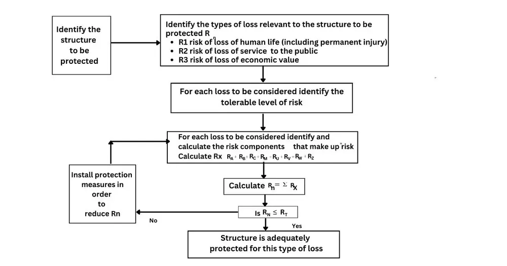
The first stage of the risk assessment is to identify which of the four types of loss (as identified in IEC 62305-1), the structure and its contents can incur. The aim of the risk assessment is to quantify and if necessary, reduce the relevant primary risks viz.
- R1- risk of loss of human life (including permanent injury)
- R2 – risk of loss of service to the public
- R3 – risk of loss of cultural heritage
- R4 – risk of loss of economic value.
R4 is considered for representative purpose only in accordance with Table 4 of IEC 62305-2: 2010. For each of the first three primary risks, a tolerable risk (RT) is set. This data can be sourced in Table 7 of IEC 62305-2.
All the major structures / buildings in the TCL plant have been evaluated for risk assessment using the flowchart.
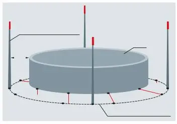
Risk Assessment from the tank farm Area.
When producing, processing, storing, and transporting flammable substances (e.g., fuel, alcohol, liquid gas, explosive dusts) in chemical and petrochemical industrial plants, potentially explosive atmospheres often come into being in which it is imperative to avoid all sources of ignition which may cause an explosion. The relevant safety regulations describe the risk for such plants posed by atmospheric discharges (lightning strikes). In this context, it is important to note that there is a risk of fire and explosion resulting from direct or indirect lightning discharge since in some cases these plants are widely distributed. To ensure the required plant availability and safety, a conceptual procedure is required to protect parts of electrical and electronic installations of process plants from lightning currents and surges
Our Experience
Client
HPCL
Client Location
Suryapet, Telangana ,India
Project
Lightning Risk Assessment
Client
GEIC
Client Location
Qatar
Project
QP FEED MIC PORT 6