A Fire and Gas Mapping Study (FGMS) is a comprehensive evaluation performed in Industrial Facilities such as Oil and Gas installations, Petrochemical Plants, Refineries, and Chemical Processing Plants. The objective of the study is to identify potential fire and gas hazards, evaluate the efficacy of existing fire and gas detection and protection systems, and optimize safety measures to reduce the likelihood of fire and gas-related incidents.
Fire and Gas (F&G) Mapping is crucial in Industrial Facilities, especially in high-risk Industries like Oil and Gas, Petrochemicals, Refineries, and Chemical Plants. The significance of F&G Mapping lies in its capacity to improve safety and reduce the associated risks of fire and gas hazards.
Key reasons why F&G Mapping is Important:
- Comprehensive Hazard Identification: F&G Mapping enables a comprehensive evaluation of potential fire and gas release scenarios within a Facility. By identifying and analyzing these dangers, businesses can gain a better understanding of the risks they confront and develop suitable safety measures.
- Optimizing Safety Measures: Through F&G Mapping, businesses can assess the efficacy of their current fire and gas detection and protection systems. This evaluation contributes to the optimization of safety measures, ensuring that the Facility is sufficiently outfitted to respond to emergencies.
- F&G Mapping enables the establishment of response zones and emergency plans, thereby enhancing emergency response. By mapping the locations of potential hazards and identifying secure evacuation routes, emergency response teams are able to act swiftly and effectively in the event of a fire or gas release.
- Preventing Incidents from Escalating: Early detection of fire and gas hazards enables prompt intervention. This can prevent incidents from escalating, thereby minimizing property, asset, and environmental damage.
- Protecting Human Lives: F&G Mapping’s primary objective is to protect human lives. During emergencies, early warning and prompt evacuation procedures can save lives.
- Reducing Financial Losses and Downtime: By minimizing the impact of fire and gas-related incidents, F&G Mapping contributes to the reduction of operational disruptions and associated financial losses.
- Many Industries are subject to stringent safety regulations and standards that mandate F&G Mapping. Compliance ensures that businesses adhere to legal and industry best practices.
- Risk Assessment and Prioritization: F&G Mapping enables a systematic risk assessment, allowing businesses to prioritize safety enhancements based on the severity and probability of potential hazards.
- Environmental Protection: F&G Mapping aides in preventing harmful gas leaks and releases in Industries that handle hazardous substances.
- Strengthening Safety Culture: F&G Mapping demonstrates an organization’s commitment to safety. It contributes to the development of a safety-conscious culture among employees, contractors, and stakeholders.
- Ongoing Enhancement: F&G Mapping is not a one-time activity. Periodic updates and evaluations aid in preserving the efficacy of safety measures and identifying opportunities for continuous improvement.
Therefore, F&G Mapping is indispensable for ensuring the safety and protection of Personnel, Assets, and the environment in Industrial Facilities. It enables companies to proactively manage fire and gas hazards, reduce risks, and respond to emergencies, contributing to safer and more reliable operations.
During the design phase, a F&G mapping study must be conducted to ensure that the detector coverage objectives are met and that the current F&G arrangement is adequate to meet its intended design performance.
In addition, during normal Facility operations, the F&G mapping study should be conducted whenever there are significant alterations or modifications. Therefore, the study must determine whether or not this arrangement is still suitable for continuous operation. If this is not the case, a list of recommendations to improve FGS performance must be provided and considered.
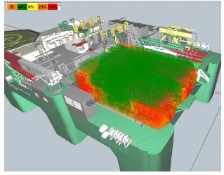
Typically, a 3D simulation software (e.g. Detect 3D) is used to perform this F&G mapping study while accounting for apparatus and structure obstructions. A F&G mapping investigation is bolstered by comparing detector coverage to the coverage objective.
Standards and guidelines for conducting F&G mapping studies include:
- NFPA 72: National Fire Alarm and Signaling Code,
- API RP 14C: Recommended Practice for Analysis, Design, Installation, and Testing of Safety Systems for Offshore Production Facilities,
- NFPA 72E: Standard on Fire and Gas Detectors and Sensors,
- BS EN 54: Fire detection and fire alarm systems,
- ISO 16530-1: Petroleum and natural gas Industries – Well integrity for operations on or offshore, etc.
Significance of undertaking F&G Mapping?
- F&G Mapping permits the designer to position flame and gas detection devices at intervals within the facility and assess the coverage afforded by the system. This can be mechanically correlative against pre-specified targets that the system should achieve.
- F&G Mapping provides designers with the methodology and tools to review detection coverage against pre-determined targets, and guarantee that an appropriate and optimized system is commissioned.
F&G mapping software’s that are commonly in use are:
- PHAST (Process Hazard Analysis Software),
- FLACS (Flame and Gas Modeling Software),
- DNV GL G-FETT (Gas Fire and Explosion Tool),
- SMOKEVIEW, Fire Dynamics Simulator (FDS),
- ANSYS Fluent, and Safeti (Quantitative Risk Assessment Software).
The key objectives of a Fire and Gas Mapping Study include:
- Hazard Identification: Identifying potential fire and gas release scenarios that could occur within the Facility. This includes assessing process operations, equipment, storage areas, and other potential sources of ignition or gas leaks.
- Consequence Analysis: Evaluating the consequences of potential fire and gas release scenarios, including the extent of fire spread, dispersion of hazardous gases, and potential impact on Personnel, Environment, and Assets.
- Fire Detection and Protection Analysis: Assessing the effectiveness of existing fire detection and protection systems, such as fire alarms, fire suppression systems, and fireproofing measures.
- Gas Detection and Monitoring Analysis: Evaluating the coverage and performance of gas detection systems used to monitor and detect the presence of flammable and toxic gases in the Facility.
- Mapping of Hazards and Response Zones: Creating visual representations (maps) of the Facility to indicate areas with potential fire and gas hazards and identifying response zones for emergency management.
- Risk Assessment: Quantifying the level of risk associated with various fire and gas scenarios and prioritizing risk reduction measures.
- Recommendations: Providing recommendations for improving fire and gas safety, such as the installation of additional fire and gas detection systems, the enhancement of existing systems, or the implementation of new safety protocols.
Typically, Process Engineers, Safety Engineers, Fire Protection Specialists, and other relevant stakeholders collaborate on this study. By conducting a Fire and Gas Mapping Study, Industrial Facilities can improve their safety measures, reduce the likelihood of incidents, and safeguard Personnel, Assets, and the surrounding environment more effectively in the event of a fire or gas release. In high-risk Industries, it is an essential component of a comprehensive safety management system.
The Fire and Gas (F&G) System Life Cycle refers to the different stages involved in the life span of an F&G system, from its initial conception and design to its decommissioning or replacement. Each stage of the life cycle plays a crucial role in ensuring the effective and reliable performance of the F&G system.
The typical stages of the F&G system life cycle are as follows:
Conceptualization and Planning:
- In this stage, the need for an F&G system is identified based on the potential fire and gas hazards in the Facility or process.
- Stakeholders determine the scope, objectives, and requirements of the F&G system to meet safety and regulatory standards.
- A conceptual plan for the F&G system is developed, outlining its key components and functionality.
Design and Engineering:
- Engineers and specialists design the detailed layout and architecture of the F&G system.
- They select appropriate fire and gas detectors, alarms, actuators, and other components based on the hazard analysis and system requirements.
- The design phase also includes determining the communication protocols, integration with other safety systems, and redundancy features.
Procurement and Installation:
- Once the design is finalized, the necessary equipment and components are procured from vendors.
- The installation team installs and configures the F&G system in the Facility according to the approved design and safety standards.
Commissioning and Testing:
- The F&G system is subjected to comprehensive testing and commissioning to verify its proper installation and functionality.
- Functional tests, integration tests, and performance tests are conducted to ensure the system operates as intended.
Operational Phase:
- During the operational phase, the F&G system continuously monitors the Facility for fire and gas hazards.
- It alerts Personnel through alarms and other notifications when any hazardous conditions are detected.
- Routine maintenance, testing, and calibration of the F&G system are performed to ensure its ongoing reliability.
Maintenance and Upgrades:
- Regular maintenance activities are carried out to keep the F&G system in optimal working condition.
- As technology advances or the Facility’s needs change, upgrades and enhancements may be performed to improve the system’s performance and features.
Decommissioning or Replacement:
- Eventually, the F&G system may reach the end of its useful life or become obsolete due to changing requirements or technology advancements.
- At this stage, the system is decommissioned or replaced with a new and more advanced F&G system to maintain the Facility’s safety standards.
Throughout the F&G system life cycle, proper documentation, training, and adherence to safety standards are critical to ensuring the effectiveness and reliability of the system in protecting the Facility, Personnel, and Assets from fire and gas hazards.
Fire and gas detection systems offer several significant advantages that contribute to enhanced safety and protection in Industrial Facilities, commercial buildings, and other environments.
Some of the key advantages of F&G detection systems include:
- Early Warning and Rapid Response: Fire and gas detection systems provide early warning of potential fire and gas hazards, enabling prompt and efficient response measures. Early detection allows occupants and Personnel to evacuate safely and initiate emergency procedures, reducing the risk of injuries and fatalities.
- Life Safety: The primary advantage of fire and gas detection systems is the protection of human lives. By alerting occupants to hazardous conditions, these systems significantly increase the chances of timely evacuation, minimizing the impact of fire and gas-related incidents on Personnel.
- Property Protection: Fire and gas detection systems help safeguard valuable Assets, equipment, and property from damage or destruction caused by fires or gas leaks. Early detection and timely response can prevent the spread of fires and minimize property losses.
- Environmental Protection: In Industries dealing with hazardous substances, gas leaks can lead to environmental pollution and harm to the surrounding ecosystem. Effective gas detection helps identify and contain gas leaks, reducing the risk of environmental contamination.
- Reduced Downtime and Losses: Timely detection and intervention can prevent incidents from escalating and causing prolonged downtime. This helps in reducing financial losses associated with operational disruptions and damage to equipment.
- Integration with Fire Suppression Systems: Fire detection systems can be integrated with fire suppression systems, allowing for automatic activation of sprinklers, gas-based suppression systems, or other fire suppression measures. This coordinated response helps control or extinguish fires before they spread and cause significant damage.
- Continuous Monitoring: Fire and gas detection systems continuously monitor the environment for potential hazards, even in unmanned or remote areas. This provides round-the-clock protection, which is especially beneficial for critical facilities that operate 24/7.
- Compliance with Safety Regulations: Many Industries are subject to strict safety regulations and standards that mandate the installation of fire and gas detection systems. Compliance ensures that companies adhere to industry best practices and legal requirements.
- Proactive Risk Management: Fire and gas detection systems contribute to proactive risk management by identifying potential hazards and enabling preventive measures to reduce the likelihood of incidents.
- Improved Safety Culture: Implementing fire and gas detection systems demonstrates a commitment to safety within the organization. It fosters a safety-oriented culture among employees, contractors, and stakeholders.
- Real-time Monitoring and Alerts: Fire and gas detection systems often include remote monitoring capabilities, allowing operators and safety Personnel to receive real-time alerts and notifications. This enables a quick response, even if the Facility is unmanned.
In summary, fire and gas detection systems are critical safety measures that provide early warning, protect human lives, safeguard property, and promote a safe working environment in various settings. The advantages of these systems help Industries prevent, mitigate, and respond effectively to fire and gas-related hazards, minimizing potential risks and ensuring a safer working environment for all stakeholders
Fire and gas detector mapping study provides an objective analysis of detector layouts to support the design method and optimize the amount of detectors required to satisfy coverage targets.
iFluids Engineering with our subject matter expertise ensures our CLIENTs, competent experts & resources for carrying out the step by step approach for F&G Mapping study.