Introduction
Haya Water, a registered trademark of Oman Wastewater Services Company is an Omani closed joint-stock Company, wholly owned by the government of the Sultanate of Oman. Haya Water is a government organization responsible to develop, design, implement, operate and maintain the wastewater facilities in Muscat.
Haya Water is steadily advancing to implement one of the largest engineering projects in the field of treating wastewater and looking forward to accomplish its primary goal by promoting higher health standards for all. This is achieved by reducing the pollution caused by conventional wastewater systems, preventing the spread of diseases, epidemics and protecting ground water resources from contamination.
Haya Water operations lead to the production of environmental eco-friendly treated water, which will maintain the water reservoir for future generations as well as reduce the use of expensive desalination water associated with CO2 emissions, and contribute positively in the economic growth and improve food security, in addition to producing high quality eco-friendly fertilizers which contributes directly to enhancing the agricultural sector.
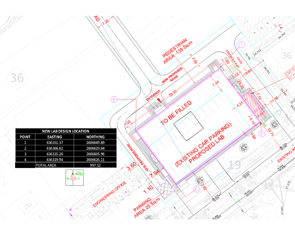
As part of expansion of its operations, Haya water have decided to expand Haya Water Central Laboratory at Al Ansab as a stand-alone and to be used as Central Laboratory near the Operation Building in the STP.
Central Laboratory tests samples of various industrial liquids such as treated water, potable water, drinking water etc.
iFluids was appointed as the Consultant to perform preliminary design of laboratory and its ancillaries.
Brief Scope of Work
HayaWater awarded this project as FEED and it consists of the following activities:
- Conduct a preliminary study of the existing laboratory and its requirements.
- Design a new laboratory building which can accommodate all the existing laboratory equipments.
- Preparation of EPC tender documents.
- Assisting Haya Water in obtaining local approvals.
After EPC work is awarded, support EPC contractor.
Project Objective
The main objective of this project is to provide the prelimimary design of the new standalone laboratory. Approximately 1000 sqm area shall be utilized to accommodate the proposed design of Laboratory with all associated facilities.
Discipline Involved:
- Civil & Architecture
- MEP
- Electrical
- Telecom
- Lab Specialist (Consultant)

Scope was to design a laboratory with state-of-art facilities. HayaWater intends the building to be eco-friendly and the design need to be carried out in such a way that it consumes less energy. Also, the building has to be technologically advanced in terms of safety and security. All these points were considered in designing the building.
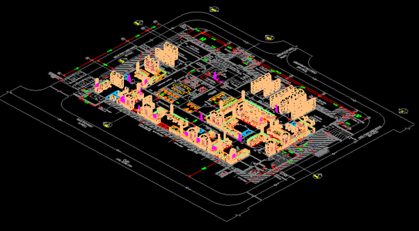
Once project was awarded, a brief site survey was carried out by respective discipline in-charges. Existing data were collected and carried out the design activities for the proposed laboratory were conducted in Chennai office. As in every infrastructure project, primary deliverables were from civil department.
Civil and architectural team developed the building design complying Haya Water as well as International Standards. Once the design work of the building was completed, other disciplines prepared all the respective deliverables as per the requirements.
Scope of MEP services was to design utilities such as HVAC, drainage, plumbing, firefighting etc. An MEP co-ordination layout was also prepared in the final stage by combining all utility drawings to avoid clashes.
Electrical department designed the electrical system for the whole building. UPS sizing, cable sizing etc were carried out during the design period. Power consumption of all the existing equipments were collected during site survey.
Fire detection and telecom system were designed by the Instrument & telecom department. Also, the safety and security system of the whole building was also designed by telecom. This includes CCTV, ACS system, PA/GA system and fire detection system.
For the laboratory design, since iFluids doesn’t have in-house specialist, service of a third party consultant was utilized. A close co-ordination with specialist was carried out in successful completion of the project.
Deliverables from all the departments were submitted and obtained approval.
List of Deliverables
| Sl. No | Description |
| CIVIL & ARCHITECTURAL | |
| 1 | Master layout Plan |
| 2 | Ground Floor layout |
| 3 | First Floor layout |
| 4 | Terrace Floor layout |
| 5 | Section & Elevation |
| 6 | Floor Tiling Layout |
| 7 | Finishing Schedule |
| 8 | Architectural Typical Details |
| 9 | Schedule of Doors and Windows / Details |
| 10 | Reflected ceiling layout |
| 11 | Technical BOQ for Architectural items |
| 12 | Civil Technical Specifications |
| 13 | Utility services layout |
| BUILDING MECHANICAL SERVICES | |
| LABORATORY FUME HOOD & CASEWORK | |
| 1 | Fume hood and Case work-Plan Ground Floor |
| 2 | Fume hood and Case Work-Equipment Layout Ground Floor |
| 3 | Fume hood and Case work -Isometric View |
| 4 | Technical Specification for laboratory fumehood & case work |
| 5 | Technical BOQ for laboratory fumehood & case work |
| LABORATORY GAS DISTRIBUTION & UTILITY | |
| 1 | Lab Gas Distribution System – P&ID View – Ground Floor Sheet 1 of 3 |
| 2 | Design Basis Report for gas distribution system |
| 3 | Technical Specification for compressed air, gas distribution & utility system |
| 4 | Technical BOQ for gas distribution system |
| 5 | Lab Gas Distribution System – Ground Floor Plan |
| HVAC SERVICES | |
| 1 | HVAC DBR |
| 2 | HVAC Calculations |
| 3 | HVAC Layout- Ground |
| 4 | HVAC Layout- Roof |
| 5 | VRF Piping Schematic |
| 6 | HVAC Airflow Schematic-Laboratory Area |
| 7 | HVAC Fresh Air Schematic |
| 8 | HVAC MTO |
| 9 | HVAC- Technical Specification |
| LABORATORY EXHAUST SYSTEM | |
| 1 | Laboratory Exhaust System – Ground Floor |
| 2 | Laboratory Exhaust System – Roof |
| 3 | Design Basis Report for laboratory exhaust system |
| 4 | Technical Specification for laboratory exhaust system |
| 5 | Technical BOQ for laboratory exhaust system |
| PLUMBING SERVICES | |
| 1 | Plumbing Layout-Ground |
| 2 | Plumbing Layout-Terrace |
| 3 | Plumbing Calculations |
| 4 | Plumbing DBR |
| 5 | Technical Specifications-Plumbing |
| 6 | MTO-Plumbing |
| 7 | Plumbing Schematic |
| DRAINAGE SERVICES | |
| 1 | Drainage DBR |
| 2 | Drainage Calculation |
| 3 | Technical Specifications-Drainage |
| 4 | MTO – Drainage |
| 5 | Drainage Layout – Ground |
| 6 | Drainage Layout- Roof |
| 7 | Drainage Schematic |
| FIRE FIGHTING SYSTEM | |
| 1 | Internal Fire Protection Layout |
| 2 | Fire MTO |
| 3 | Fire Equipment Specifications |
| 4 | External Fire Hydrant Layout |
| 5 | Fire DBR |
| 6 | Fire Systems Calculations |
| 7 | Fire evacuation plan |
| MEP CO-ORDINATION LAYOUT | |
| 1 | MEP Co-Ordination Layout -Ground |
| 2 | MEP Co-Ordination Layout -Terrace |
| INSTRUMENTATION/TELECOM | |
| 1 | Datasheet for F&G devices |
| 2 | Specification for F&G System |
| 3 | Datasheet for F&G cables |
| 4 | Riser diagram |
| 5 | Typical Installation drawing |
| 6 | F&G location layout-Ground |
| 7 | F&G Cable routing Layout-Ground |
| 8 | Cable Schedule |
| 9 | F&G MTO |
| 10 | Block Diagram for CCTV System |
| 11 | Cable Routing Layout-CCTV System |
| 12 | Block Diagram for ACS System |
| 13 | Cable Routing Layout-ACS System |
| 14 | Block Diagram for Telecom System |
| 15 | Cable Routing Layout-Telecom System |
| 16 | Block Diagram for speaker System |
| 17 | Cable Routing Layout-Speaker System |
| ELECTRICAL SYSTEM | |
| 1 | Main Single Line Diagram – New |
| 2 | UPS Single Line Diagram |
| 3 | HVAC DB Single Line Diagram |
| 4 | Lighting DB Single Line Diagram |
| 5 | Power DB Single Line Diagram |
| 6 | Electrical Design Basis |
| 7 | Electrical Load List |
| 8 | Electrical Power and Control Cable Schedule |
| 9 | LV Cable Sizing Calculations |
| 10 | Earthing Calculations |
| 11 | UPS Sizing Calculations |
| 12 | Lighting Calculations |
| 13 | Lightning Protection Calculations |
| 14 | Cable Tray Sizing Calculations |
| 15 | Data Sheet for LV Switchboard |
| 16 | Data Sheet for LV Power and Control Cables |
| 17 | Data Sheet for AC UPS |
| 18 | Data Sheet for Distribution Boards |
| 19 | Electrical Equipment Layout – Electrical Room |
| 20 | Cable Routing Layout – Ground Floor |
| 21 | Lighting Layout – Ground Floor and Peripheral Lighting |
| 22 | Earthing Layout – Ground Floor |
| 23 | Typical Installation Drawings for Cabling |
| 24 | Typical Installation Drawings for Lighting |
| 25 | Typical Installation Drawings for Earthing and Lightning Protection |
| 26 | Material Take Off (MTO) |
Constraints
One of the main constraints of the project was about the building requirement. Hayawater intended to construct an archive building and IT center on the top of laboratory building. However, it was not confirmed/finalized during the design stage. Due to this, iFluids were not able to calculate exact power consumption requirement of the building. In addition to this, other discipline deliverables were also affected. However, it was informed to Haya Water about this constraint and they confirmed that it will be the responsibility of EPIC contractor to finalize the building and power requirement.
Another constraint was the delay in obtaining concurrence/approval from client. This happened in the earlier stage of the project as we were not able to identify the correct contact person for the project. Once it was identified we were able to obtain approval for the documents and close the project.
One more constraint which arised in the due course of design was regarding the scope of work. In the awarded tender, it was written to conduct preliminary engineering or FEED. However, at times, client was on the idea that we are doing detailed engineering. Even though we discussed and sorted this issue across the table, it was done very lately.
Another constraint was lack of existing drawings. Drawings of existing laboratory or the location were not available. This resulted in delay of the project.
Obtaining approval from Oman local authority was also a point of concern. However, client requested only technical support for approval.
Lesson Learned
- A single point of contact at client side need to be identified before commencement of any project. Frequent communication with the person need to be maintained.
- In the preliminary stage of the project itself, all concerns regarding the exact scope of work need to be discussed with client. This discussion points to be recorded with their concurrence.