PROJECT OBJECTIVES
The objective of this project is to provide Detailed Design for:
- Ventilation Calculation for Deluge Skid
- Heater Calculation
- Ventilation Layout for Deluge skid
METHODOLOGY
iFluids Engineering has been awarded a Detailed Design Engineering Contract, to propose a ventilation system for the Deluge skid by considering the heat load calculations of all equipment in a skid and to select a suitable ventilation design structure by performing the ventilation calculations.
Considering skid location and site conditions, the ventilation calculation and ventilation layout is prepared. Based on design assumptions from the project scope, the ventilation calculation is performed as per the relevant standards and guidelines. Based on the ventilation calculation, Exhaust air fan (Ventilation equipment used for the deluge skid) capacity is designed and proposed, as per Manufacturer Standard for the future implementations.
VENTILATION CALCULATION
Size of Skid = 11 m Length X 3 m Width X 2.5 m height
Area of the Skid = 11 m x 3 m = 33 Sqm.
Minimum requirement of air flow = 2.7 M3/hr per Floor Area
So, Total air flow = 2.7 x 33 = 89.1 M3/hr = ~ 90 M3/hr
As per Manufacturer Standard, the minimum capacity of Exhaust fan is around 800 M3/hr. Hence the same has been selected.
Exhaust air Fan Capacity = 2 Nos of 800 M3/hr considered (1 Working + 1 stand by) along with Fresh air side, Fresh air Louver with Pre-filter and Motorized on/off type VCD, are considered.
HEATER CALCULATION WITH RESPECT TO SELECTED FAN CAPACITY
Minimum Outside air temperature = -10°C = 263°K
Inside Skid temperature = 5°C = 278°K
Heater Capacity (Q) = m x Cp x ΔT
Where,
Mass flow rate = Volume flow rate x Density of air
Volume Flow rate = 800 M3/hr
Density of air = 1.225 Kg/m3
Cp = Specific Heat of air = 1.005 KJ / Kg °K
ΔT = Temperature Difference = 15 °K
Heater Capacity (Q) = m x Cp x ΔT
= 800 (M3/hr) x 1.225 (Kg/m3) x 1.005 (KJ / Kg°K) x 15 °K
= 14773.5 KJ/hr = 4.1 KJ/s = 4.1 KW = 4100 Watts
As confirmed by Client, Selected Heater Capacity is 8000 Watts (i.e 4 Nos of 2000 W)
HVAC SYSTEM DESCRIPTION
VENTILATION FANS – Wall Mounted Propeller Fan
Wall mounted propeller exhaust fan has been considered for the deluge skid Enclosure.
Wall mounted propeller fan Shaft is made of steel, accurately ground and of ample size for the load transmitted, and does not pass through first critical speed through the full range of specified fan speeds.
- Accessories: The following accessories were provided with propeller fans:
- Wire guard on inlet side and bird screen at the outlet.
- Gravity louvers built into a steel frame at the outlet.
- Regulator for controlling fan speed for single-phase fan motor.
- Single phase preventer for 3 phase fans.
- All fans were selected for the lowest operating noise level.
- The HVAC equipment were designed and selected to minimize the transmission of noise and vibration. Noise level in deluge skid rooms shall not exceed 35 dBA. The air distribution systems and all air devices were selected to maintain minimum noise criteria. The air conditioning systems were designed to minimize noise levels.
MAJOR ACCESSORIES CONSIDERATIONS
HVAC DUCT DESIGN:
Ducting was sized using equal friction method specified in ASHRAE fundamental.
Ductwork shall be constructed of galvanized sheet steel. Galvanized ductwork were designed for low velocity except where specified otherwise and were in complete conformance with the latest edition of the SMACNA HVAC Duct Construction Standards and DW144 – Specification for sheet metal ductwork heating & ventilation Contractors Association.
The duct work was designed via equal friction method considering the head loss of 1 Pa/m. Duct work air velocities shall not exceed the following limits.
- Main Duct Maximum velocity: 10 m/s
- Branch Duct Velocity: 2.5 m/s
Duct leakage test was conducted as per DW/143 – Ductwork Leakage Testing.
FILTER SECTION – Pre Filters MERV 8
High efficiency Pre filter made out of dry cleanable synthetic media with 50mm thickness shall be provided on the suction side of Fan Unit as standard equipment with the unit. The framework shall be made from environment friendly recycled paper, which is easily disposable. These filters shall have the efficiency of 90% down to 10-micron particle size. Face velocity across these filters shall not exceed 2.5 m/s.
ELECTRIC HEATER
- Heaters manufactured from Powder coated Carbon steel Construction, suitable to be installed Wall mounted / Ceiling Mounted.
- Heater Element of Finned type SS 304 Construction.
- Heater Terminal box of Powder coated die cast aluminium which is weatherproof to IP66 against water and dust.
- The heater elements were for single-phase or three-phase connection and steps of control were arranged to maintain balanced operation across phases.
HVAC CONTROL PANEL
Ventilation System shall be controlled through redundant PLC based Control panel housing all control equipment, sensors, starter-control circuits, relays to allow control of the following. The PLC backup/secondary unit shall take over automatically in the event of primary unit failure.
HVAC control Panel monitors the following parameter as minimum:
- Status of motorized dampers
- Status of Exhaust Fans
- Heater on/OFF status
- Display Deluge skid temperature
- Display ambient temperature
AIR FLOW CONTROL ACCESSORIES
- Air Inlets and Outlets – such as Supply and Return air grilles, registers and diffusers.
- Volume Control Dampers (VCD)
- Motorized Dampers
- Louvers
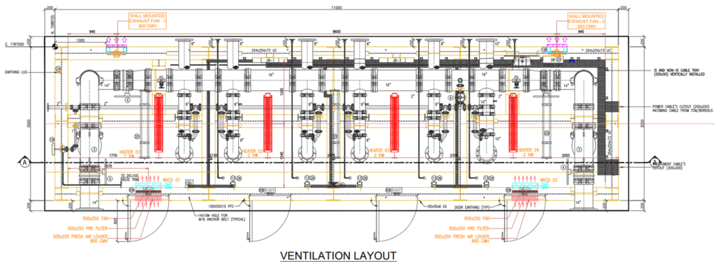
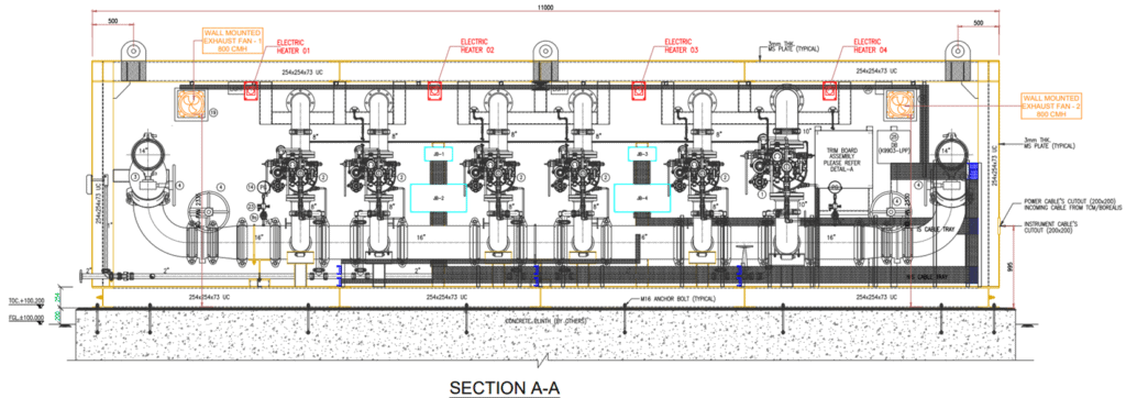
DELUGE VALVE HOUSE 1 VENTILATION LAYOUT
Layout attached below,