Qatar National Oil and Gas producing, processing and exporting company (QP) has awarded iFluids Engineering to conduct 3 years framework contract for bow-tie development and major accident hazard management (MAHM) deliverables for all onshore & offshore operational areas. QP Onshore oil and gas producing fields is situated at Dukhan on the western coast of Qatar and offshore on the north east quadrant of Qatar territorial waters.
QP is an integrated national oil corporation that stands at the forefront of efforts for the long-term sustainable development, utilization and monetization of oil and gas resources in the State of Qatar. They include the exploration, refining and production, marketing, and sale of oil and gas, LNG, NGL, GTL products, refined products, petrochemicals, fertilizers, steel and aluminium.
QP Operational areas includes
- QP’s operations and activities are conducted at various onshore locations including Doha, Dukhan, Mesaieed and Industrial Cities; and at various offshore areas, such as offshore oil field production stations, drilling platforms, Halul Oil Export Island, and the North Field, which is the largest single non-associated gas reservoir in the world covering an area of 6,000 square kilometres (km).
- Dukhan Fields measure approximately 80 km long by 12 km wide in area, containing over 650 oil, gas and water injection well heads and over 4000 km of pipelines. Dukhan field is split up into five (5) production / operating zones – Arab D, Khatiyah, Dukhan Township, Fahahil, Jaleha and Diyab.
- Qatar Petroleum’s Offshore operations have five (5) Offshore Production Stations located in the North East quadrant of Qatar territorial waters, PS-02 Maydan Mahzam (MM), PS- 03 Bul Hanine (BH), North Field Alpha (NFA), Al Morjan in Al Rayyan field and Halul Terminal.
- Refining Operations Qatar Petroleum (QP) currently owns and operates a major Refinery complex, consisting of Crude and Condensate Distillation, Residue Fluid Catalytic Cracking (RFCC), Chemicals Plant (ex-SEEF), Berth-4&6 (MIC Port) and associated downstream processing units as well as required utilities, located at Mesaieed Industrial City, 45 km south of Doha City in the State of Qatar. Qatar Petroleum Refinery (QPR) produces several products with the main products being gasoline (R91/95), Light Gas Oil (LGO), Jet fuel and LPG. Such products are primarily used to supply local consumption.
- Mesaieed Operations have four (4) NGL plants, which also include AGRU, SRU and MEROX units as well as Storage, loading, crude oil tank farm & terminal and utilities areas located at Mesaieed Industrial Area, 35 km south of Doha City in State of Qatar. Mesaieed Operations also have Gas Transmission and Distribution stations and pipeline
Scope of Work
The Scope of Work to be carried out for the next 3 years for Dukhan Fields and offshore areas, includes Technical Safety Studies such as:
Bow-Tie Analysis
A Bowtie is to assess the management of Major Hazards in order to identify the Barriers required to effectively manage these Hazards. It can be depicted in a graphical representation of how a hazard can be released, how it can escalate and how it is controlled. It defines the barriers required to effectively manage, prevent or mitigate hazards and its harmful consequences.
Bowtie analysis is a hazard analysis technique which is a combination of fault trees and event trees. Fault tree includes identification of basic events that can lead to an accident scenario (“top event”), whereas Event Tree identifies the event sequences from the initiating events up to the undesired consequences. The Bow-Tie model represents how a hazard can be released, escalate (i.e. become a consequence), and its control measures. The bow tie model also provides a systematic process for identifying and documenting how a hazard is managed.
Bow-tie approach is developed based on MAH Register in order to visualise the cause of a major accident event, likely outcomes, and measures in place to prevent, control and mitigate the hazard using a pictorial representation for easy understanding.
The approach to developing an effective Bowtie requires properly defining the scope of the Bowtie based on the complexity of the activities being evaluated.
- Each Bowtie should have a well-defined (logical) scope or boundary.
- Each Bowtie should be defined for a specific or distinct Hazard.
- Since the same Hazard may be present in multiple process units or work activities it is recommended that separate Bowties are developed where significant differences exist in location or function.
- The Threats, Top Event and Consequences must be relevant to the scope being considered.
- It should be realized that Consequences (e.g. fire, explosion) may not be confined to one area and may impact surroundings and result in consequential damage. If propagation of the Consequence is credible those scenarios should be analysed and added to the Bowtie as appropriate.
- The level of detail within the Bowtie should be commensurate with the complexity of the scope and scenario(s) being considered (e.g. entire asset/facility, process units, and work activities). The Bowtie analysis should be scoped in such a way that the results of the bowtie have sufficient clarity and detail that information on Barriers and SCE can be effectively implemented in the field. An example of Best Practice would be to set the scope of the Bowtie at the Unit level in an operating Asset.
- As Barrier validity is more critical than the number of Barriers, the focus should not be placed on the number of Barriers; rather on the identification of truly valid (effective, independent and auditable) Barriers.
Hardware Barriers and Human Barriers, or combinations thereof, written in a Bowtie should be those that we can provide assurance to or verify the validity of; Barrier ownership is critical for the successful management of Major Hazards
Major Accidents and Hazard Management studies (MOPO)
MOPO matrix is a visually coded manual used to define whether a work activity can be conducted safely within a given condition (e.g. within darkness). A particularly common area of concern that is addressed by MOPOs is whether two activities can be conducted safely at the same (referred to as simultaneous operations, or SIMOPs).
A matrix of permitted operations (MOPO) is an information tool to assist Supervisors and Line Managers during the planning and coordination of operations and activities. These summaries help to provide employees or safety managers with information regarding the relative importance of a particular safety control to individual operational processes within the workplace. This allows the worker to ascertain whether work may proceed without the control in place or to determine that a control needs to be restored or added into the operational system in order for that particular work to be able to continue.
The MOPO is a set of matrices that maps operational activities against foreseeable situations that if or when they arise could compromise safe operating limits – these situations are identified from:
- The Threats and Escalation Factors identified as part of the Bow-tie assessments for severity 5 and high risk hazards.
- An assessment of other operations and activities that could contribute to the escalation of an incident, e.g. continuing with hot work when fire pumps (a safety critical element (SCE)) are unavailable.
It is conducted as a workshop and facilitated by a person with relevant experience in the type of activities to be carried out and also experienced in acting as a chairperson for a workshop attended by a group of experienced personnel in various disciplines. Node Definition
The following aspects are analysed and recorded in the SIMOPS/MOPO Matrix workshop:
- Identify all construction, dismantling/demolition, pre-commissioning, commissioning and start up production operations, sub-surface drilling/well intervention activities that may potentially be concurrently undertaken at the same time.
- Identify if there is a potential hazard associated with the two operations occurring simultaneously.
- Describe the normal safeguards required by the safety management systems that are applicable before any particular operation can be performed, e.g. PTW.
- Identify possible restrictions (if any), which if in place, over and above the existing safety management systems, may enable the two independent operations to occur concurrently.
- The proceedings of the SIMOPS shall be recorded in an agreed format. Typically an Excel file is used by majority of the stakeholders.
Technical Site Survey
Safety barriers are defined as physical and/or non-physical means planned to prevent, control, or mitigate undesired events or accidents. They may range from a single technical unit or human actions, to a complex socio-technical system. Process safety barrier have an important role to maintain the operational integrity of the components when they are in operation and also to mitigate any hazardous scenarios which might cause due to the process upset conditions. A five steps approach is proposed in this work which can be used to assess and optimize the existing technical safety barrier while using the human (i.e. operator) as an extra safety barrier.
The following are some of the elements that needs to be verified during the technical site survey:
- Plant and process equipment design basis / philosophy
- Pressure Vessels
- Heat Exchangers
- Tanks
- Process containment system (All)
- Piping Systems Design / Inspection / Repair
- Pipeline Design / Inspection / Repair
- Temporary Repair Philosophy / Practices
QRA
Quantified Risk Assessment (QRA) is a technique for detailed assessment of risk. It is typically applied to major hazard industrial sites where the nature of the hazards encourages a detailed understanding of risk as an aid to risk management.
QRA involves simulation of the processes and activities, and will often involve the use of advanced computer modelling tools to simulate the consequences of hazard scenarios and evaluate the likelihood of events. It can be used to estimate impairment frequencies of equipment e.g. emergency equipment or high risk escalation sources (e.g. risers) and also financial and environmental impacts
Results are calculated and presented as numerical estimates of risks:
- To individuals – employees, contractors and members of the public, and
- To groups of people i.e. societal risk.
The QRA model will identify the major hazard contributors to work force, third parties; quantify risks; also identify and assess any risk reduction methods that may be proposed.
In addition to modelling the current situation within the scope, the model will be extendible to add additional facilities as development occurs and provide an active method of planning any proposed development.
The model will include;
- Examination of all hydrocarbon / toxic material related events.
- Quantification of the likelihood of hydrocarbon / toxic material events.
- Quantification of the consequences of hydrocarbon / toxic material incidents.
- Combination of consequences and likelihood of events to give a risk profile for individuals, and assets.
- Identify the current levels of risk to the personnel within the facility, societal risk for public, and the QP assets.
- A land usage study; which can be used for future development planning. Identify LSIR contours for the safe location of new facilities within the plant area.
- Identification and assessment of risk reduction solutions.
Demonstration of ALARP that the risks have been reduced
Vehicle Impact Assessment
Vehicle Impact Assessment is a comprehensive study directed at generating a qualitative and quantitative understanding of the implications of locating pressurized gas pipelines in various locations.
Vehicle impact are considered to arise either from internal vehicle movements within the site or from external vehicles which lose control and breach the site boundary at sufficient speed to cause a significant impact.
It is the method for systematically quantifying the risks to the public, considering the effects of the pipeline-roadway synergy, including effects on the pipeline failure rate as well as consequences of possible failure including ignition by vehicles.
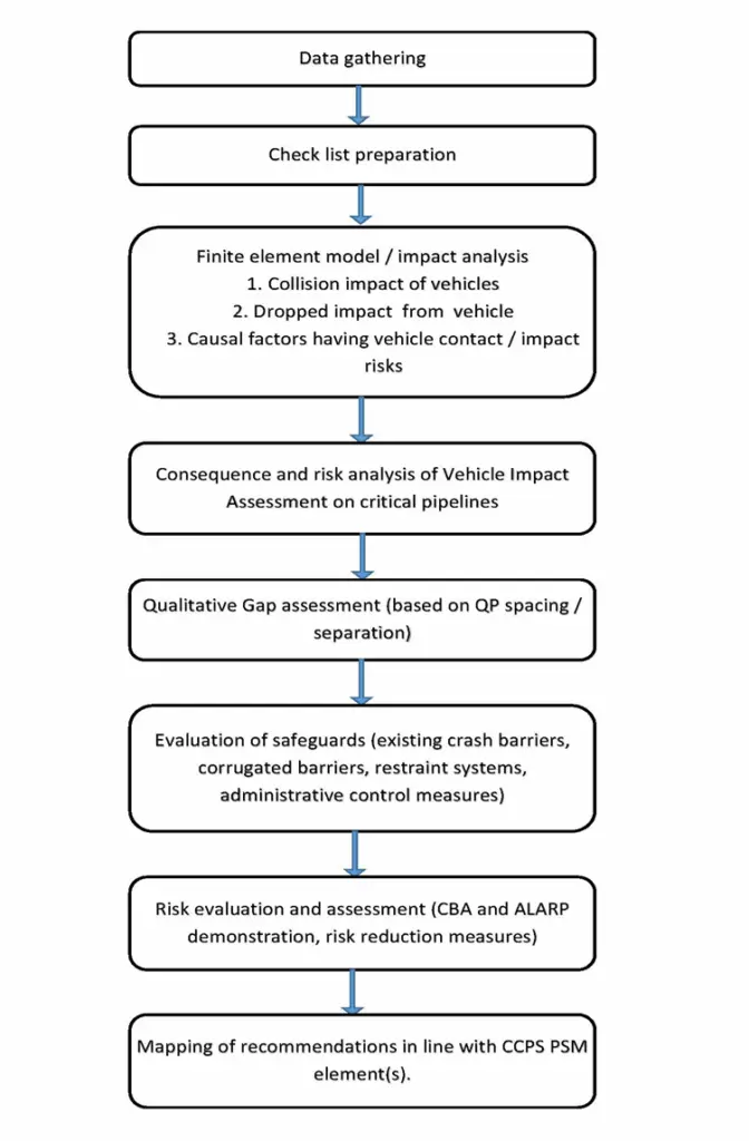
The most important objective of the Vehicle Impact Assessment study is to analyze:
- Collision impact of vehicles with the pipelines on vulnerable locations
- Dropped impact from vehicles falling off from bridges and culverts onto critical pipelines, wherever applicable
- All other causal factors having vehicle contact / impact risks e.g. vehicles passing over pipelines / legal crossing
- The step by step procedure for Vehicle Impact Assessment on critical pipelines is described below
Major Accidents and Hazard Management studies
The MAH Risk Register contains a wealth of information describing a Facility’s or Project’s hazards and associated hazard management controls. Because of the esoteric nature of the register, different forms of presenting the same information are used to support the communication and management of major hazards. The different presentation methods, and their relationships, are presented in Figure 2. This methodology on the development of MAH Risk Register.
The Major Hazard and Risk Register contains information describing the controls required to manage hazards. Providing this information to Operations and Major Project personnel generates the awareness which is a precursor to identifying steps towards selecting opportunities to reduce risks.
Completion Period
The period of completion of project is 3 years.
Deliverables
- Shall submit the findings of the technical survey to QP through audio-visual presentation to QP
- The technical survey report of all process safety barriers, detailed by department and asset, and the current risk status of the process safety barriers such as
- Overview of process safety
- Terms of Reference (ToR) for methodology of execution
- Literature review findings
- Location acceptability review findings
- Minimum separation distance review findings
- Record of all inadequacies and propose recommendations
- Mapping of recommendations against the relevant CCPS and PSM element